TECHNICAL
LEEP Mats are generally constructed of Douglas
Fir Grade 1 lumber. Mats are put through a rigorous
inspection process prior to being assigned a grade
and becoming available for use.
Call for Rental Info
LEADING EDGE
EQUIPMENT PARTNERS
(206) 999-1503
USED MATS
• Condition: Very Good
• General Use: – Crane Mats
– Digging Mats
– Outrigger Pads
• Condition: Good
• General Use: – Crane Mats
– Digging Mats
– Outrigger Pads
• Condition: Fair
• General Use: – Access Mats
– Digging Mats
AGRADE
BGRADE
CGRADE
3. What is nominal
driving resistance?
When piles are driven into the ground, the
load that is applied consists of two types of
loads: (1) dynamic load, and (2) static load.
Dynamic load results from the propagation
of stress waves along the body of the pile
and thus the load due to driving becomes
greater than the static load – which is
mainly the load from the superstructure.
Consequently, the soil resistance that
opposes pile movement into the ground
during driving is higher than the soil resistance
required to support the design loads
from the superstructure once the structure
is built. According to AASHTO 2014,
Commentary C10.7.3.7, the mobilized soil
resistance during pile driving is called the
Nominal Driving Resistance (Rndr) which
should be greater than or equal to the sum
of the factored loads divided by the resistance
factor jdyn (considering no down drag
and no scour forces for simplicity). Thus:
Rndr = (ΣgiQi)/jdyn ………… (1)
Where, ΣgiQi is the factored load per pile
(MFSLSL)
According to FHWA 2016 Section 2.10,
the maximum factored resistance for a
given pile type is the lesser of the factored
structural resistance and the factored
geotechnical resistance for that pile.
Geotechnical resistance is the resistance
offered by the soils, PWR and rock whereas
structural resistance is the resistance
offered by the steel section without any
damage to the steel. The MFSLSL must not
be greater than the MFSR of piles which
is the allowable load the structural steel
can safely take without exceeding half
the yield stress of steel. For example, the
MFSR of HP 12x53 for Grade 50 Steel ( fy =
50 ksi) would be (15.5 in2 x 50 kips/in2)*0.5
= 387.5 kips, where Resistance Factor=0.5
and Steel Area of the HP12x53 section
is 15.5 in2.
When a pile is founded in soils, the
geotechnical resistance generally becomes
less than the structural capacity of the
steel and therefore, the maximum factored
resistance, i.e., the Nominal Driving
Resistance (NDR) is what controls the
design. However, when the pile is founded
on rock like materials such as PWR or bedrock,
the geotechnical capacity generally
exceeds the structural capacity and therefore,
structural capacity controls the design
(AASHTO 2014, Article 10.7.3.2.3).
From soil dynamics, it can be explained
why the driving resistance in soils is greater
than the post-construction static resistance.
In rock-type materials that behave
like a refusal medium, driving of piles
becomes difficult and driving resistance
is not practically mobilized. Geotechnical
bearing capacity far exceeds the structural
capacity of pile materials, which control
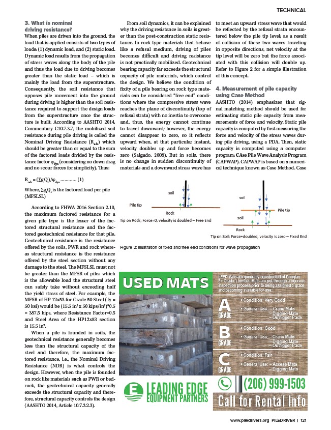
the design. We believe the condition of
fixity of a pile bearing on rock type materials
can be considered “free end” conditions
where the compressive stress wave
reaches the plane of discontinuity (top of
refusal strata) with no inertia to overcome
and, thus, the energy cannot continue
to travel downward; however, the energy
cannot disappear to zero, so it reflects
upward when, at that particular instant,
velocity doubles up and force becomes
zero (Salgado, 2008). But in soils, there
is no change in sudden discontinuity of
materials and a downward stress wave has
to meet an upward stress wave that would
be reflected by the refusal strata encountered
below the pile tip level; as a result
of collision of these two waves traveling
in opposite directions, net velocity at the
tip level will be zero but the force associated
with this collision will double up.
Refer to Figure 2 for a simple illustration
of this concept.
4. Measurement of pile capacity
using Case Method
AASHTO (2014) emphasizes that signal
matching method should be used for
estimating static pile capacity from measurements
of force and velocity. Static pile
capacity is computed by first measuring the
force and velocity of the stress waves during
pile driving, using a PDA. Then, static
capacity is computed using a computer
program: CAse Pile Wave Analysis Program
(CAPWAP). CAPWAP is based on a numerical
technique known as Case Method. Case
Figure 2: Illustration of fixed and free end conditions for wave propagation
www.piledrivers.org PILEDRIVER | 121
/www.piledrivers.org