prior to ground improvement. Four “cells”
designated by column and row headings
(e.g., B3, C3) in the middle of each pile
group were selected to represent a theoretically
uniform level of ground improvement
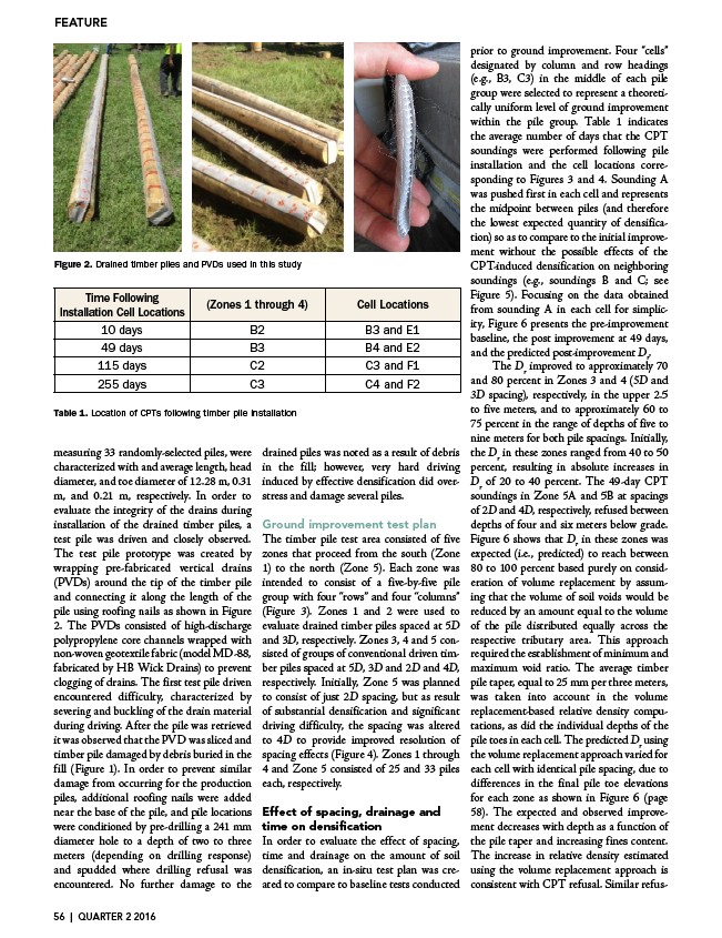
within the pile group. Table 1 indicates
the average number of days that the CPT
soundings were performed following pile
installation and the cell locations corresponding
to Figures 3 and 4. Sounding A
was pushed first in each cell and represents
the midpoint between piles (and therefore
the lowest expected quantity of densification)
so as to compare to the initial improvement
without the possible effects of the
FEATURE
Drained timber piles and PVDs used in this study
Location of CPT’s following timber pile installation.
Figure 2. Drained timber piles and PVDs used in this study
Table 1. Location of CPT’s following timber pile installation.
Figure 2. Drained timber piles and PVDs used in this study
Table 1. Location of CPT’s following timber pile installation.
Figure 2. Drained timber piles and used in this study
Time Following
Installation Cell Locations
(Zones 1 through 4) Cell Locations
10 days B2 B3 and E1
49 days B3 B4 and E2
115 days C2 C3 and F1
255 days C3 C4 and F2
Installation Cell Locations
Following Installation Cell Locations
Time Following Installation Cell Locations
(Zones 1 through 4)
CPT-induced densification on neighboring
soundings (e.g., soundings B and C; see
Figure 5). Focusing on the data obtained
from sounding A in each cell for simplicity,
Figure 6 presents the pre-improvement
baseline, the post improvement at 49 days,
and the predicted post-improvement Dr.
Cell Locations
(Zones 5A and 5B)
(Zones 1 through 4)
The Dr improved to approximately 70
10 days B2 B2 B3 and E1
B3 and E1
49 days B3 B3 B4 and E2
B4 and E2
115 days Table 1. Location of CPTs C2 following timber pile installation
C2 C3 and F1
C3 and F1
255 days C3 C3 C4 and F2
C4 and F2
measuring 33 randomly-selected piles, were
characterized with and average length, head
diameter, and toe diameter of 12.28 m, 0.31
m, and 0.21 m, respectively. In order to
evaluate the integrity of the drains during
installation of the drained timber piles, a
test pile was driven and closely observed.
The test pile prototype was created by
wrapping pre-fabricated vertical drains
(PVDs) around the tip of the timber pile
and connecting it along the length of the
pile using roofing nails as shown in Figure
2. The PVDs consisted of high-discharge
polypropylene core channels wrapped with
non-woven geotextile fabric (model MD-88,
fabricated by HB Wick Drains) to prevent
clogging of drains. The first test pile driven
encountered difficulty, characterized by
severing and buckling of the drain material
during driving. After the pile was retrieved
it was observed that the PVD was sliced and
timber pile damaged by debris buried in the
fill (Figure 1). In order to prevent similar
damage from occurring for the production
piles, additional roofing nails were added
near the base of the pile, and pile locations
were conditioned by pre-drilling a 241 mm
diameter hole to a depth of two to three
meters (depending on drilling response)
and spudded where drilling refusal was
encountered. No further damage to the
Cell Locations
(Zones 5A and 5B)
(Zones 1 through 4)
drained piles was noted as a result of debris
in the fill; however, very hard driving
induced by effective densification did overstress
and 80 percent in Zones 3 and 4 (5D and
3D spacing), respectively, in the upper 2.5
to five meters, and to approximately 60 to
75 percent in the range of depths of five to
nine meters for both pile spacings. Initially,
the Dr in these zones ranged from 40 to 50
percent, resulting in absolute increases in
Dr of 20 to 40 percent. The 49-day CPT
soundings in Zone 5A and 5B at spacings
of 2D and 4D, respectively, refused between
depths of four and six meters below grade.
Figure 6 shows that Dr in these zones was
expected (i.e., predicted) to reach between
80 to 100 percent based purely on consideration
1
1
and damage several piles.
5
B
Ground improvement test plan
The timber pile test area consisted of five
zones that proceed from the south C
(Zone
A
1) to the north (Zone 5). Each zone was
intended to consist of a five-by-five pile
of volume replacement by assuming
group with four “rows” and four 9 “columns”
4
that the volume of soil voids would be
(Figure 3). Zones 1 and 2 were used to
reduced by an amount equal to the volume
evaluate drained timber piles spaced at 5D
of the pile distributed equally across the
and 3D, respectively. Zones 3, 4 and 5 consisted
respective tributary area. This approach
of groups of conventional driven timber
required the establishment of minimum and
piles spaced at 5D, 3D and 2D and 4D,
maximum void ratio. The average timber
respectively. Initially, Zone 5 was planned
pile taper, equal to 25 mm per three meters,
to consist of just 2D spacing, but as result
was taken into account in the volume
of substantial densification and significant
replacement-based relative driving difficulty, the spacing was altered
sketch density computations,
of cell B2 to 4D to provide improved resolution of
Zones 1 through spacing effects (Figure 4). Zones 1 through
4 and Zone 5 consisted of 25 and 33 piles
of 5 to 9 m for both pile spacings.each, respectively.
Initially, the Dr in these zones ranged from 40 to 50%,resulting in absolute increases in Effect Dr of of spacing,20 to drainage 40%.and
The 49-day CPT soundings in Zone and 5B at spacings of 2D and 4D,time on densification
In order respectively,to evaluate the effect refused of spacing,
between depths of 4 and 6 m below
grade. Figure 6 shows that Dr in time these and drainage zones on the was amount expected of soil
(i.e., predicted) to reach between
80 to 100% based purely on consideration densification, an in-situ of test plan volume was created
replacement by assuming that volume of soil voids would be reduced by an amount equal to the volume of the distributed equally across the respective tributary area. This approach required plan
Figure 4. In-situ test plan for Zone 5 Figure 5. Enlarged
sketch of cell B2 in
Zones 1 through 4
as did the individual depths of the
pile toes in each cell. The predicted Dr using
the volume replacement approach varied for
each cell with identical pile spacing, due to
differences in the final pile toe elevations
for each zone as shown in Figure 6 (page
58). The expected and observed improvement
spacings. Initially, the Dr in these zones ranged from 40 to 50%,
increases in Dr of 20 to 40%. The 49-day CPT soundings in Zone 5A
decreases with depth as a function of
4D, respectively,refused between depths of 4 and 6 m below
the pile taper and increasing fines content.
The increase in relative density estimated
using the volume replacement approach is
consistent with CPT refusal. Similar refus-
that Dr in these zones was expected (i.e., predicted) to reach between
purely on consideration of volume replacement to compare to baseline by tests assuming conducted
that the
would be reduced by an amount equal to the volume of the pile
across the respective tributary area. This approach required the
Cell Locations
(Zones 5A and 5B)
10 days B2 B3 and E1
49 days B3 B4 and E2
115 days C2 C3 and F1
255 days C3 C4 and F2
Figure 3. In-situ test plan
for Zones 1 through 4
5
C
B
A
9 4
1
5
C
B
A
9 4
Figure 4. In-situ test plan for Zone 5 Figure 5. Enlarged
In-situ test plan
Zones 1 through 4
Figure 4. In-situ test plan for Zone 5 Figure 5. Enlarged
sketch of cell B2 in
Zones 1 through 4
for both pile spacings. Initially, the Dr in these zones ranged from 40 to 50%,
absolute increases in Dr of 20 to 40%. The 49-day CPT soundings in Zone 5A
spacings of 2D and 4D, respectively,refused between depths of 4 and 6 m below
Figure 6 shows that Dr in these zones was expected (i.e., predicted) to reach between
based purely on consideration of volume replacement by assuming that the
soil voids would be reduced by an amount equal to the volume of the pile
equally 56 across | QUARTER 2 the 2016
respective tributary area. This approach required the